This post comes with the feedback of OBDSTAR X300 Pro4 about what cars can work, what cars cannot work.
X300 Pro4 works list:
Audi:
Audi A4/ A5/ A6/ Q3/ Q4/ Q5/Q7 key programming-ok
Chevrolet:
Chevrolet corolado 2016 program IMMO- OK
Citroen:
Latest shape Citroen C1 2014 Registered car key program- ok
2004 Citroen c2 key program-ok
Ford:
2013 Ford focus all keys lost -ok
2015 Chrysler 200 read pin code-ok
2012 Buick Enclave remote program-ok
Infinity:
2006 infinity g35 4 door sedan-ok
Jeep:
2002 Jeep grand Cherokee Laredo- ok
KIA:
Kia Sportage (China) 2015 2016 smart key program-ok
Land Rover:
Freelander 2, 2008 diesel key programming-ok
Nissan:
2017 Nissan Sentra key programming-ok
Hyundai:
Hyundai Tucson 2017 add key-ok
Renault:
Renault talisman 2017 blank key all key lost-ok
Renault Can Clip tool add Renault models Scenic, Grand Scenic key-ok
Renault Trafic +2014 id47 code key- ok
Vaxhall:
vaxhall astra h mk5 2004 read pincode-ok
X300 PRO4 cannot work:
Clio IV 2018 all key lost-No
2004 Ford C-Max all keys lost- No
2018 Honda Crv all keys lost-No
2009 HE22S Suzuki Lapin all keys lost- No
Q: Does X300 PRO4 contain Key renew?
A: No, it doesn’t.
Q: Does x300 pro4 only program the original factory key?
A: No. Other brand keys also are supported.
Q: Can X300 pro4 program Indian cars?
A: Yes, it can.
Q: Does X300 pro4 comes with Toyota simulated smart keys?
A: No, it doesn’t include smart card.
Q: Does X300 PRO4 support Chrysler 200 (2015) smart key programming?
A: It supports Chrysler smart key programming in American and Canadian region.
Q: What year does x300 pro4 support on UK ford fiestas?
A: The following car models car supported.
Blade 2003-2012
Blade 2008-2012
Blade 2002-2008
PROXIMITY 2018-
PROXIMITY 2012-2017
PROXIMITY 2008-2012
Q: What European Ford cmax are supported by X300 Pro4?
A: The cmax models below are supported.
BLADE 2015-
BLADE 2010-2014
BLADE -2011
BLADE -2010
PROXIMITY 2015-
PROXIMITY 2010-2014
Q: Can x300 pro4 do 4th and 5th generation MQB VW and Toyota g and h chips?
A: It can support 4th above add keys. Only support a part of dash types for all keys lost.
All the G and H chip models of Toyota in Central ASIA and American support adding keys and all keys lost
2020年6月15日星期一
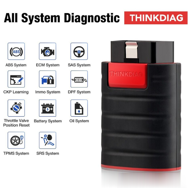
Can Launch ThinkDiag Reset Tire Pressure for 2015 Chevrolet Suburban
Customer question: I have a 2015 Chevy Suburban, the tires get low, I
want to replace the wheels. I see the tire pressure icon is on the
dash. Is possible to reset tire pressure by Launch Thinkdiag? How to do?
Obd2tool.com engineer replied:
Yes. Launch Thinkdiag OBD2 scanner is a good choice. It not only supports basic diagnosis but also contains 15 kinds of reset service incl. reset TPMS.

It’s easy to use. Please follow the step-by-step guide below to operate:
1. Download, register, activate ThinkDiag APP
Step 1: When receiving ThinkDiag device, you need to download ThinkDiag APP in APP store or Google Play on Android or IOS smartphone.
If you cannot search the APP, click this link to download free directly: https://www.mythinkcar.com/apk/Thinkdiag.apk
Step 2: After installing, open APP to register with email address, verification code and password.
Step 3: Then login with your available username and password
Step 4: Enter main menu to select “Me” and then choose “activation”
Step 5: Input the serial number and activation code from the password paper comes with Thinkdiag device package.
Step 6: After activating, you can get two free car software in ThinkStore. Choose GM and another car manufacturer.
2.Reset Tire Pressure by ThinkDiag
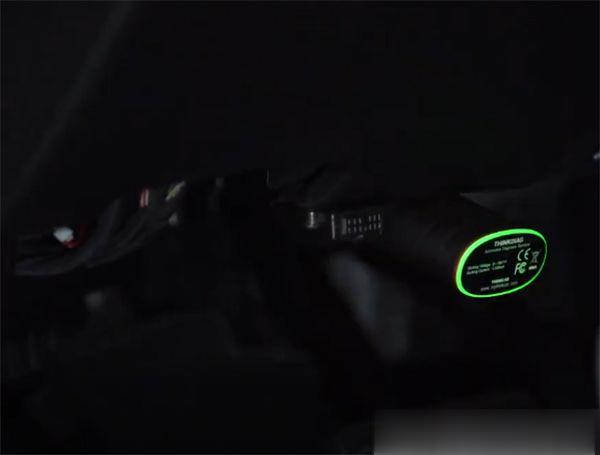
Plug the ThinkDiag device into OBDII port in your vehicle
When the green light appears on the ThinkDiag that indicates the device is powered on

Turn the ignition on
Run ThinkDiag APP
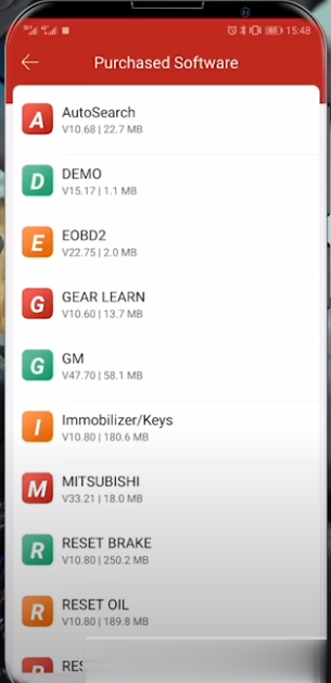
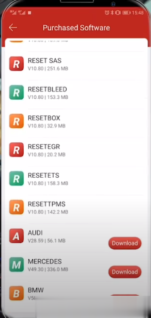
Select ThinkStore-> Purchased software
There are two ways to select the corresponding car model.
Method 1: Select GM, and it will let us do all of the GM in Chevy vehicles

Method 2: Select Reset TPMS which is a tire pressure modulated

Here selects method 2 to operate.
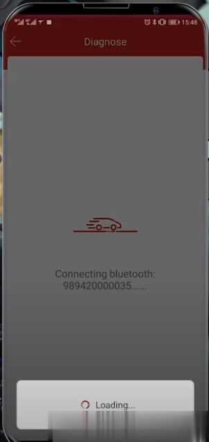
Connecting Bluetooth automatically

Note: When you hear the beep that means it’s connected.
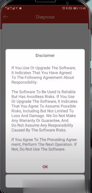
It will show the disclaimer as below, just click OK to continue

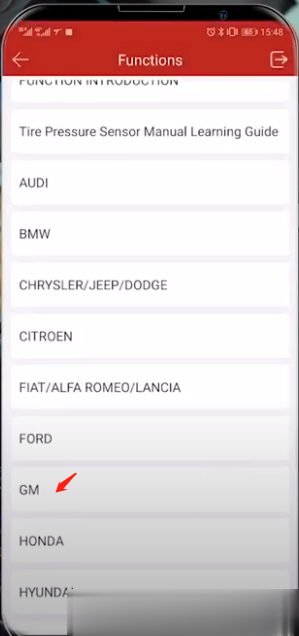
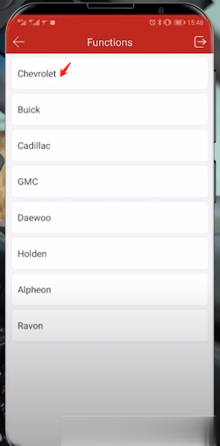
Then select the corresponding car brand –GM

Make sure the ignition switch is on
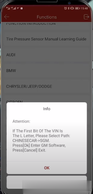
Pay attention to the path info to enter GM software

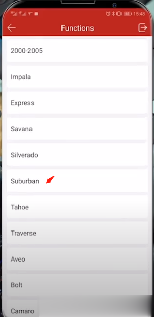
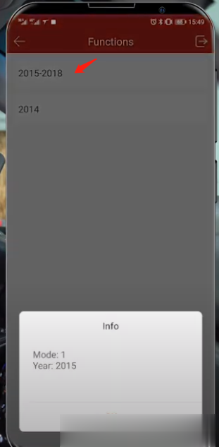
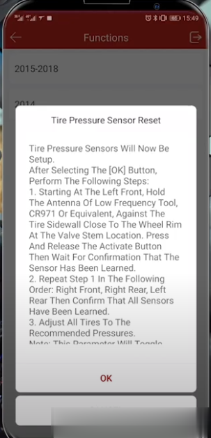
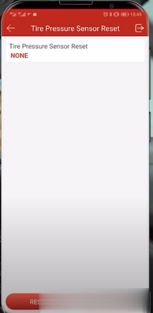
Select Chevrolet->Suburban-> 2015-2018


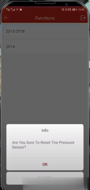
Make sure to reset tire pressure

Follow the Tire Pressure Sensor Reset instruction on-screen to operate

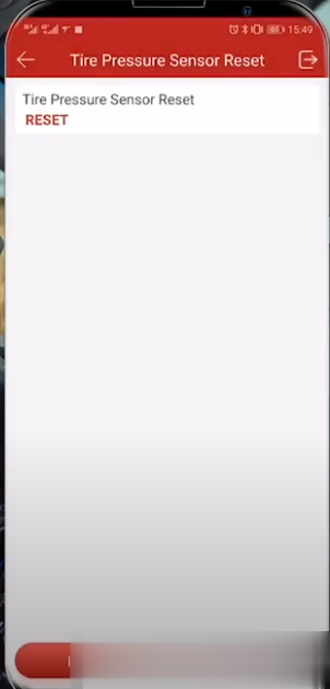
Select the Reset button at the bottom
You will see the status go from none to reset, thatmeans it’s reset.
thinkdiag-reset-tpms-2015-chevy-suburban-14


Obd2tool.com engineer replied:
Yes. Launch Thinkdiag OBD2 scanner is a good choice. It not only supports basic diagnosis but also contains 15 kinds of reset service incl. reset TPMS.
It’s easy to use. Please follow the step-by-step guide below to operate:
1. Download, register, activate ThinkDiag APP
Step 1: When receiving ThinkDiag device, you need to download ThinkDiag APP in APP store or Google Play on Android or IOS smartphone.
If you cannot search the APP, click this link to download free directly: https://www.mythinkcar.com/apk/Thinkdiag.apk
Step 2: After installing, open APP to register with email address, verification code and password.
Step 3: Then login with your available username and password
Step 4: Enter main menu to select “Me” and then choose “activation”
Step 5: Input the serial number and activation code from the password paper comes with Thinkdiag device package.
Step 6: After activating, you can get two free car software in ThinkStore. Choose GM and another car manufacturer.
2.Reset Tire Pressure by ThinkDiag
Plug the ThinkDiag device into OBDII port in your vehicle
When the green light appears on the ThinkDiag that indicates the device is powered on
Turn the ignition on
Run ThinkDiag APP
Select ThinkStore-> Purchased software
There are two ways to select the corresponding car model.
Method 1: Select GM, and it will let us do all of the GM in Chevy vehicles
Method 2: Select Reset TPMS which is a tire pressure modulated
Here selects method 2 to operate.
Connecting Bluetooth automatically
Note: When you hear the beep that means it’s connected.
It will show the disclaimer as below, just click OK to continue
Then select the corresponding car brand –GM
Make sure the ignition switch is on
Pay attention to the path info to enter GM software
Select Chevrolet->Suburban-> 2015-2018
Make sure to reset tire pressure
Follow the Tire Pressure Sensor Reset instruction on-screen to operate
Select the Reset button at the bottom
You will see the status go from none to reset, thatmeans it’s reset.
thinkdiag-reset-tpms-2015-chevy-suburban-14
2020年6月1日星期一
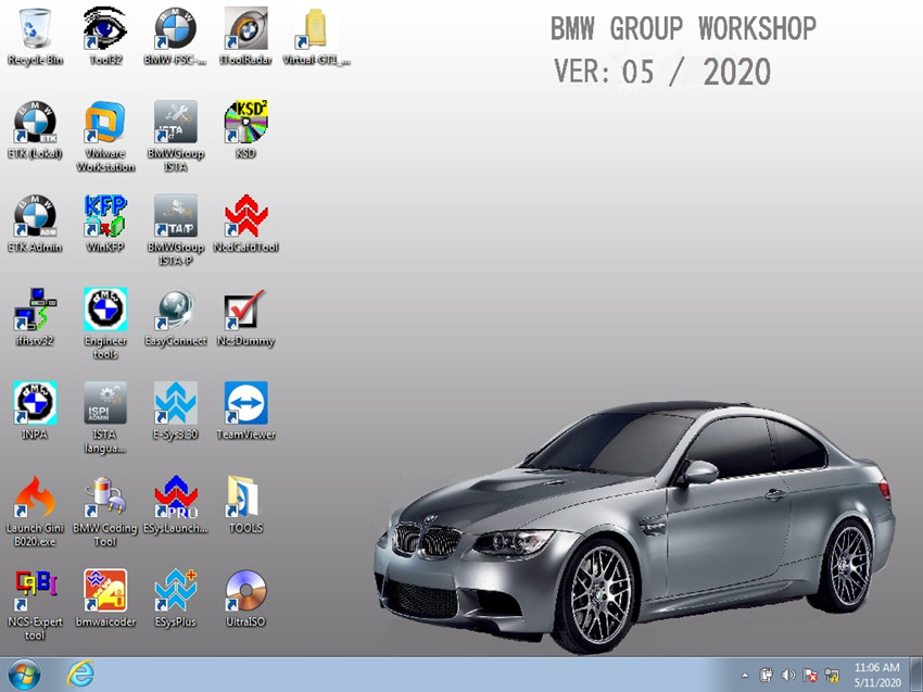
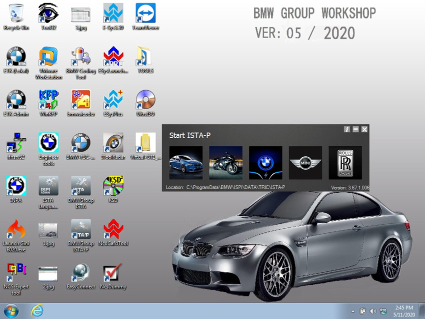
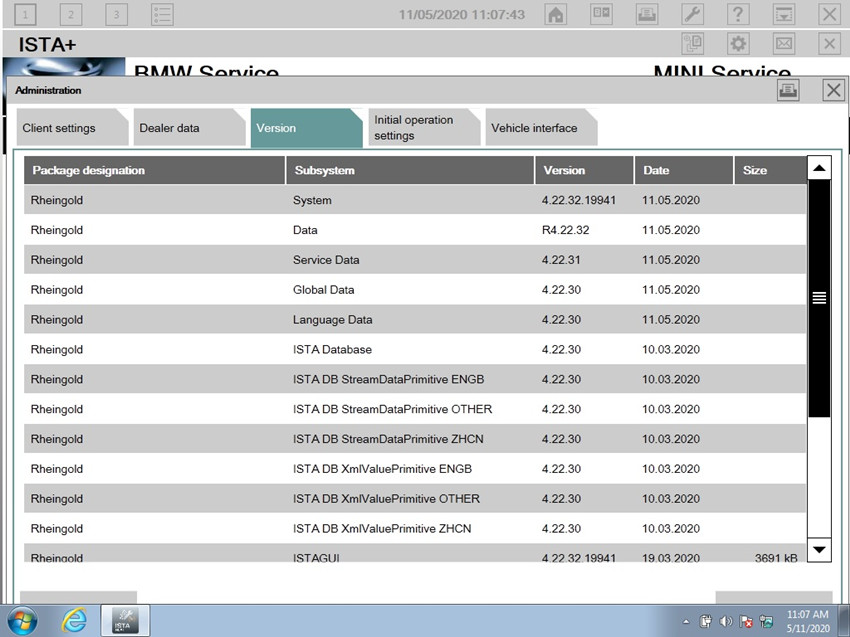
Newest 2020.05 Version BMW ICOM NEXT A +B + C,ICOM A2,A3+B+C Software Released
V2020.05 Newest Version Software ISTA-D ISTA 4.22.32 ISTA-P 3.67.1.006 with Engineer Programming
It works on BMW ICOM NEXT,BMW ICOM A2+B+C,BMW ICOM A3+B+C+D.
Software Version : V2020.05
ISTA – D: 4.22.32,with SDP Programming Database 4.22.32
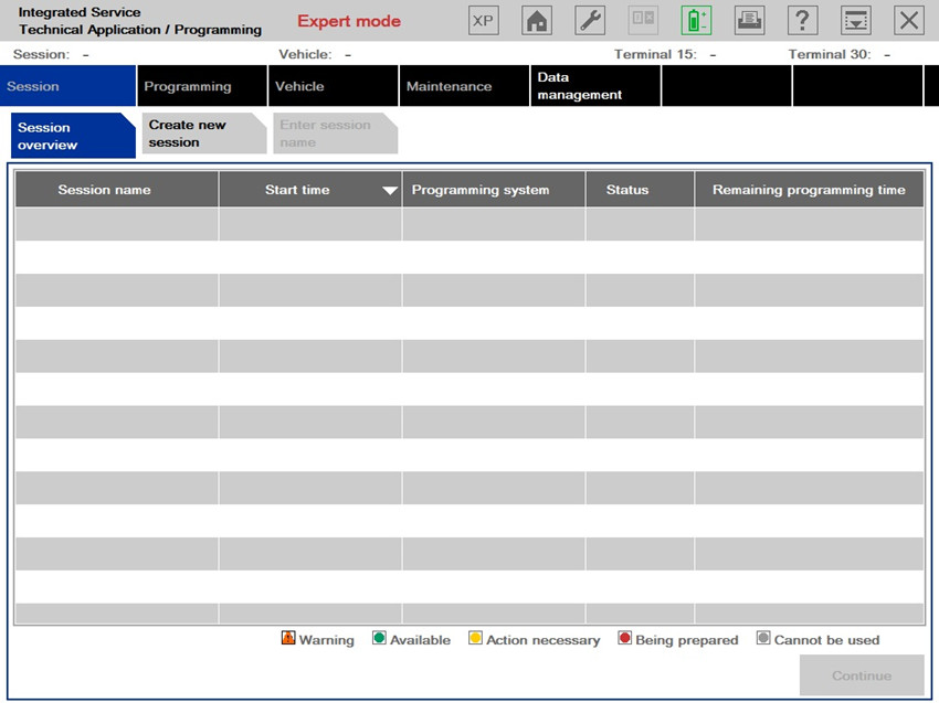
ISTA – P: 3.67.1.006 with Engineer Programming,supports the programming of BMW motorcycles and electric vehicles can program F/G/I/K chassis for car (through the ICOM, not other cable )
Vin: V2020.2.15
BMW ETK: 2020.01
BMW KSD: 2020.01 Multilanguage
BMW FSC Navigation Code Generator
BMWAiCoder for BMW Coding
BMW ICOM NEXT,A2,A3 +B +B +C V2020.05, With free Software:
ISTA-P/ISTA-D Multi-language available in diagnosing, programming and TIS diagram circuit: British English, German, Spanish, French, Italian, polish, Portuguese, Turkish, Czech, Swedish, Dutch, Indian, Greek, Russian, Simplified Chinese, Traditional Chinese, Japanese, Korean and Thai.
BMW ICOM software display:
It works on BMW ICOM NEXT,BMW ICOM A2+B+C,BMW ICOM A3+B+C+D.
Software Version : V2020.05
ISTA – D: 4.22.32,with SDP Programming Database 4.22.32
ISTA – P: 3.67.1.006 with Engineer Programming,supports the programming of BMW motorcycles and electric vehicles can program F/G/I/K chassis for car (through the ICOM, not other cable )
Vin: V2020.2.15
BMW ETK: 2020.01
BMW KSD: 2020.01 Multilanguage
BMW FSC Navigation Code Generator
BMWAiCoder for BMW Coding
BMW ICOM NEXT,A2,A3 +B +B +C V2020.05, With free Software:
- Get engineer version, INPA 5.00,winkfp 5.2.3,NCS 3.5.1, e-sys 3.30,data V67.0
- get Chinese software DR.GINI B020
- get count code navigation tool software FSC operator code
- get one-clik hidden brush tool BMWAi V4.6
- Add DIS Software for Old cars, DISV57 and DISV44,diagnosis and programming for BMW virtual machines
- Support Vehicles: For BMW Cars,For BMW Motorcycle,For Rolls-Royce, For Mini Cooper
ISTA-P/ISTA-D Multi-language available in diagnosing, programming and TIS diagram circuit: British English, German, Spanish, French, Italian, polish, Portuguese, Turkish, Czech, Swedish, Dutch, Indian, Greek, Russian, Simplified Chinese, Traditional Chinese, Japanese, Korean and Thai.
BMW ICOM software display:
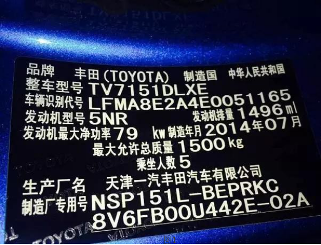
2014 Toyota“Fault Code”C1515 “Torque sensor zero adjustment is not complete” Operation method
Test car model:
Function Instruction:
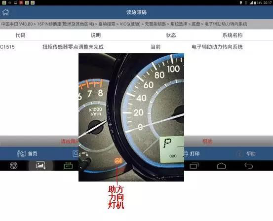
EMPSECU、Steering wheel、Tilt the steering column.、The steering column gear assembly and so on, if replaced, the direction does not help. Instrument PS warning Light, X – 431 reads to the fault code C1515 – torque sensor zero adjustment unfinished – current – electronic auxiliary power steering system fault code, as shown in figure 2, the need to operating torque sensor to adjust learning process.
Operation Procedure:
1.Switch on the ignition;
2.Select Toyota V48.80 above;
3.Select16Pin diagnostic socket;
4.Select autosearch VIOS;
5.Select no intelligent key;
6.Select chassis system;
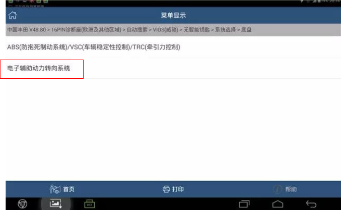
7.Select system selection;
8.Select chassis;;
9.Select Electronic auxiliary power steering system.,see pic3;
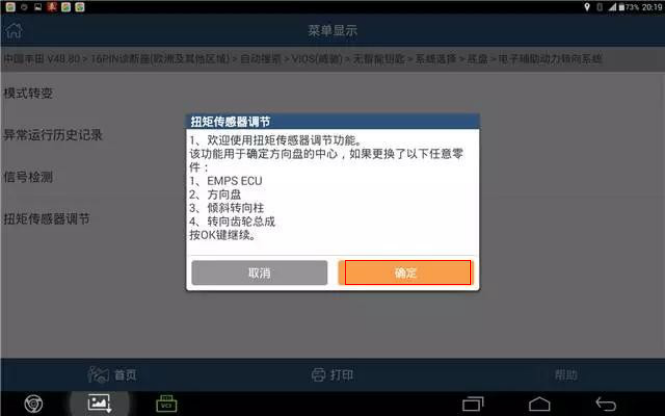
10.Select special function;
11.Select torque sensor to adjust.;
12.Note that “this function is used to adjust the position of the steering Angle, and when you use this function, please press the prompt information operation” as shown in figure 4;

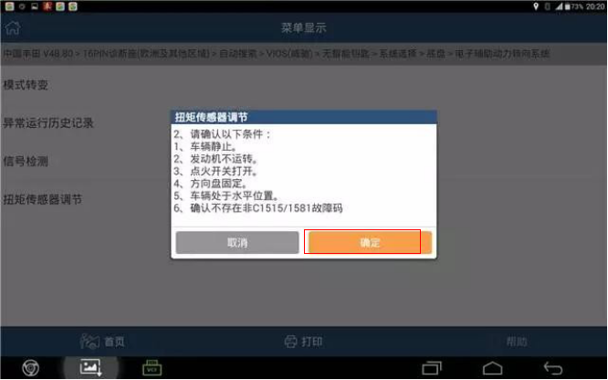
13.Note that the operating torque sensor adjusts the prompt, which is used to determine the center of the steering wheel, if any of the following parts are replaced: 1. 2.
The steering wheel. 3. Inclined steering column; 4. The steering column gear assembly shall continue as shown in figure 5 according to the “confirm” key.
14.Confirm the following: 1. The vehicle is still; 2. The engine does not run; 3. Ignition switch opens; 4. The steering wheel is fixed; 5. The vehicle is in a horizontal position; There is no non- 1515/1581 fault code in the vehicle as determined, as shown in figure 6.
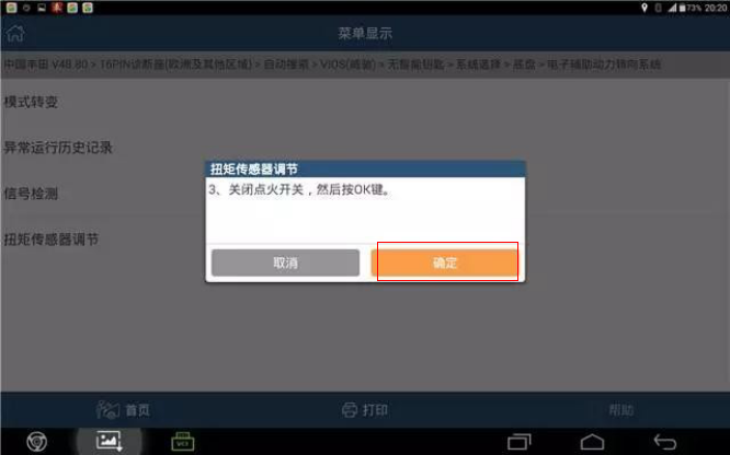
15.Switch off the ignition,then click “confirm”see as pic7;
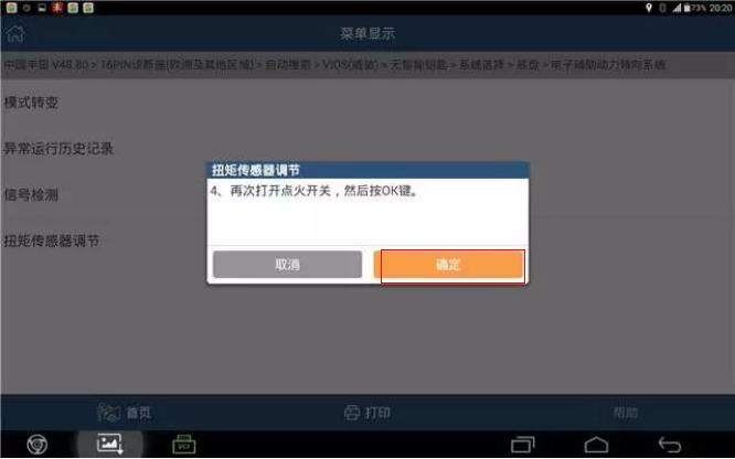
Pic7 16.Switch on the ignition again, then click “Yes”,see pic8.
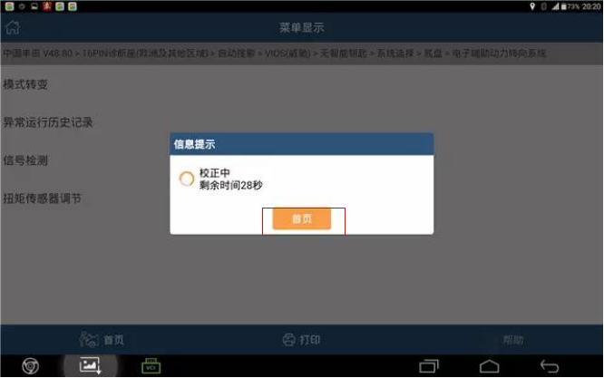
17.After the steering wheel stops swinging, press ok, indicating “correction, remaining ** seconds” as shown in FIG. 9;
18.It is suggested that “the torque sensor adjustment is completed and the PS warning lamp is turned off”, indicating that the sensor learning success is shown in figure 10.
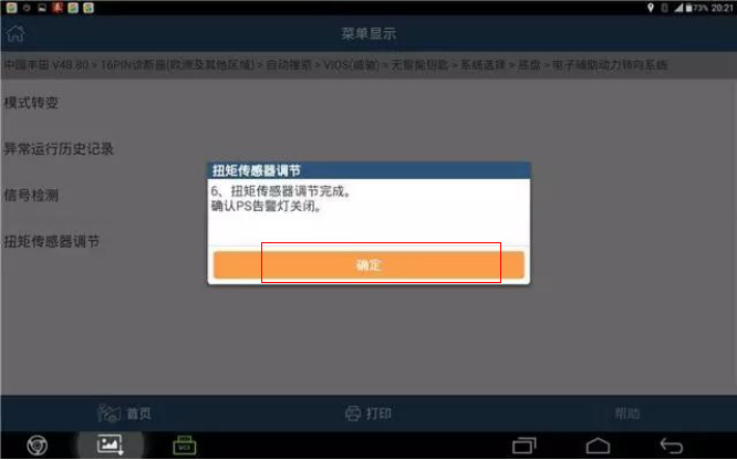
19.Press ok, exit software; Turn off the ignition switch and restart the vehicle test drive system to restore normal.
https://www.obd2tool.com/blog/2020/05/19/2014-toyotafault-codec1515-torque-sensor-zero-adjustment-is-not-complete-operation-method/
Function Instruction:
EMPSECU、Steering wheel、Tilt the steering column.、The steering column gear assembly and so on, if replaced, the direction does not help. Instrument PS warning Light, X – 431 reads to the fault code C1515 – torque sensor zero adjustment unfinished – current – electronic auxiliary power steering system fault code, as shown in figure 2, the need to operating torque sensor to adjust learning process.
Operation Procedure:
1.Switch on the ignition;
2.Select Toyota V48.80 above;
3.Select16Pin diagnostic socket;
4.Select autosearch VIOS;
5.Select no intelligent key;
6.Select chassis system;
7.Select system selection;
8.Select chassis;;
9.Select Electronic auxiliary power steering system.,see pic3;
10.Select special function;
11.Select torque sensor to adjust.;
12.Note that “this function is used to adjust the position of the steering Angle, and when you use this function, please press the prompt information operation” as shown in figure 4;
13.Note that the operating torque sensor adjusts the prompt, which is used to determine the center of the steering wheel, if any of the following parts are replaced: 1. 2.
The steering wheel. 3. Inclined steering column; 4. The steering column gear assembly shall continue as shown in figure 5 according to the “confirm” key.
14.Confirm the following: 1. The vehicle is still; 2. The engine does not run; 3. Ignition switch opens; 4. The steering wheel is fixed; 5. The vehicle is in a horizontal position; There is no non- 1515/1581 fault code in the vehicle as determined, as shown in figure 6.
15.Switch off the ignition,then click “confirm”see as pic7;
Pic7 16.Switch on the ignition again, then click “Yes”,see pic8.
17.After the steering wheel stops swinging, press ok, indicating “correction, remaining ** seconds” as shown in FIG. 9;
18.It is suggested that “the torque sensor adjustment is completed and the PS warning lamp is turned off”, indicating that the sensor learning success is shown in figure 10.
19.Press ok, exit software; Turn off the ignition switch and restart the vehicle test drive system to restore normal.
https://www.obd2tool.com/blog/2020/05/19/2014-toyotafault-codec1515-torque-sensor-zero-adjustment-is-not-complete-operation-method/
2020年5月5日星期二
How to fix 2007 vauxhall corsa no comms with GM MDI2 tech2 win
Tool to use: GM MDI2 diagnostic tool
Symptom:
Got mdi2 to connect to the gm mdi manager, but it will not communicate with a car.
using opel with Tech 2 win on the mdi2 box the tick and car lights light up for a second then go off and the pc light flashes.
when i open tech2win it asks me to select the tool so i use mdi 2
the next box asks me to select the interface but the box is blank.
I can continue but get no comms with the car.
also i have gds2 but if i open that it has no valid lease found so won’t work.
www.obd2tool.com engineer replied:
Please reinstall the MDI Manager. I uploaded it on mega (no password).
https://mega.nz/#!tFxhBYCD!agbcrCKJL5PRNiNNEw6Vj7JnsWz0F3ekuChliyeZpRs
Good luck!
How To Use Tech 2 For Service Programming System
GM Service Programming System manual:
The GM Service Programming System (SPS) is a personal computer (PC) application used to reprogram vehicle electronic control modules (ECMs). The SPS application programs General Motors programmable control modules by using the GM Tech 2 Flash scan tool or the Next Generation scan tool as a “pass-thru” device to communicate program data to the vehicle control module. All programming steps are activated and finalized through the PC
Service Programming System software CDs
GM Service Programming System kit contains two compact discs (CD):
An Application CD which loads the SPS application
A Data CD which loads SPS data
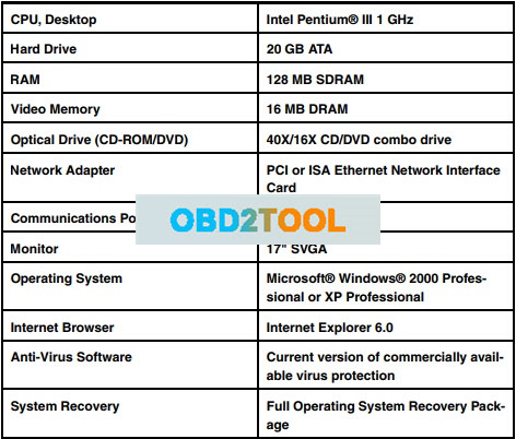
System Requirements

SPS application install
Step 1: Determine if TCP/IP protocol is installed
– If you have a network card installed then you only need to verify that TCP/IP protocol has been configured.
– If your PC is already set up with TCP/IP protocol, go to “Install the SPS Software”
Step 2: Install the SPS Application CD software
To install the SPS software, follow these steps:
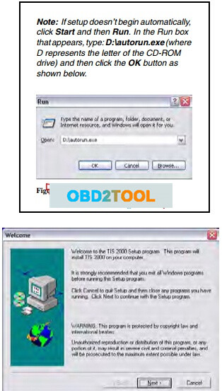
1 Insert the Application CD into the PC’s CD drive.
The TIS 2000 Installation Welcome window appears automatically (Figure 1.8).
Note: If the TIS2000 software was previous installed and removed from the PC, a message may appear asking to reuse old settings. If so, click the NO button to NOT reuse old settings.

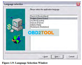
2 Click the Next button to continue. This displays the Language Selection window.

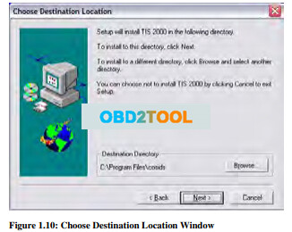
3 Select a language for the application and then click the Next button. This displays the Choose Destination Location window.

4 Click the Next button. This displays the Choose Serial Port window (Figure 1.11).
Note: Clicking the Next button on the Destination Location window places the SPS application in the destination directory C:\Program Files\cosids. You can optionally click the Browse button to select a different destination directory for the files.

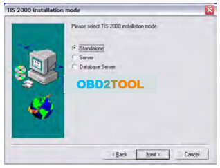
5 Select the serial port to use for the scan tool connection. This must be an open COM port where no external devices are connected. Then click the Next button. This displays the TIS2000 Installation Mode window.

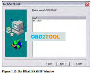
6 Select Standalone and then click the Next button. This displays the Set DEALERSHIP window.

7 Select NAO (North American Operations) and then click the Next button. This configures settings, starts the Decurity Device Installation module, and displays the TIS2000 Security Device Add / Remove window.
Note: This installation of TIS2000 supports reflash of Saturn vehicles. Other dealership installations are not supported.

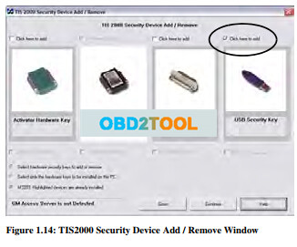
Note: The Security Device Installation module configures the USB security key, which is a component of the SPS Kit. The installation of the USB security key requires strict attention or TIS2000 will not perform as expected.
8 Click the checkbox above USB Security Key to place a checkmark in the box (Figure 1.14). Then click the Continue button. This displays an Information window (Figure 1.15).

9 Follow the instructions on the Information window and then click the OK button. This displays a Hardware Installation message box.

10 Click the Continue Anyway button. This displays the Program Completed window.

11 Install the purple USB security key as instructed on the window and then click the OK button.
Note: Make sure the security key installs securely into the PC’s USB port. After installing the software, do not remove the security key from the USB port; it must remain in the port for the TIS2000 SPS application to work.
12 This begins the TIS2000 software installation and displays a progress indicator message (Figure 1.18).
Wait for the installation to complete and for the completion message to appear (Figure 1.19).


13 Click the OK button.
14 Remove the Application CD from the PC’s CD drive.
15 Go to Update the SPS Data
Step 3: Update the data with the SPS Data CD
Note: During the update, the TIS2000 software skips the initial language, dealership, etc. steps and uses current TIS2000 settings. TIS2000 also skips over SecDevIns (Security Device Installer) and uses the current TIS2000 settings.
1 Insert the Data CD into the PC’s CD drive and wait approximately 20 seconds for the TIS2000 Update message to appear.
Note: On Windows XP systems, a browser window may open displaying the contents of the CD. If so, close the window and double-click the TIS2000 icon on the Window’s desktop. Because TIS2000 looks for new updates each time you start the application, the Update message appears.
2 Click the OK button to continue. This begins the update and displays a progress indicator message. When the update completes, a completion message appears
3 Click the OK button. The application is ready to use.
4 Begin using the SPS application by double-clicking the TIS 2000 icon located on the Window’s desktop.
Tech 2 Flash Setup
What You Will Need for Tech 2 Flash Setup:
1 The GM SPS application installed onto your PC (with the USB security key). Also see “System Requirements” on page 1
2 32 MB PCMCIA card recommended (May, 2005). Call OTC Technical Services at 800-533-6127 to determine the current minimum requirements.
3 SPS Kit Components:
RS-232 DB9 Serial Port Adapter (P/N 3000111)
RS-232 Communications Cable (P/N 3000110)
USB Security Key (already installed during software installation)
RS-232 Loop-back Adapter (P/N 3000112) User’s Guide (P/N 526933) 4 T2F Kit Components (from Tech 2 Flash Kit):
Tech 2 Flash Scan Tool
Cigarette Lighter Power Cable (P/N 3000096) or Battery Power Cable (P/N 3000097)
SAE 16/19 Pin Adapter (if the vehicle is OBD II compliant)
NAO 12/19 Pin Adapter (if the vehicle is not OBD II compliant)
(Optional) AC to DC Power Supply (P/N 3000113)
DLC Cable (P/N 3000095)
DLC Loop-back Adapter (P/N 3000110)
Step 1: Verify the Tech 2 Flash and DLC Cable (Power On Self Test – POST)
1 Make the loop-back connections as follows:
a Plug the RS-232 loop-back adapter (item 1) into the Tech 2 Flash RS-232 port. See Figure 2.1.
b Connect the DLC cable (item 2) to the GM Diagnostic Tool Tech 2 Flash VCI connector.
c Connect the DLC loop-back adapter (item 3) to the DLC cable.

2 To make the power connection, connect one of the following to the power jack on the DLC cable(see Figure 2.2. – Item 4):
battery power cable (item 1), orcigarette lighter power cable (item 2), or the optional AC to DC power supply

3 Supply power to the Tech 2 Flash.
4 Perform the Power On Self Test (POST) as detailed in the Tech 2 Flash User’s Guide.
5 The POST automatically verifies the hardware and detects any Tech 2 Flash malfunctions. Do one of the following:
If any errors are detected, refer to the POST Troubleshooting Chart located in the Tech 2 Flash User’s Guide.
If no errors are detected, go to the next step. 6 Disconnect the RS-232 loop-back adapter, the power supply, and the DLC loop-back adapter.
7 Go to the steps
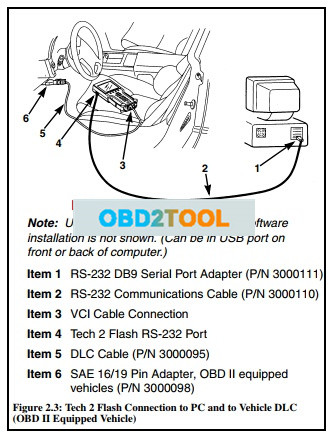
Step 2: Connect the Tech 2 Flash Scan Tool to the PC and to the Vehicle DLC
1 Connect the RS-232 DB9 serial port adapter (Item 1) to the open COM port on your PC that you selected when you installed the SPS application.
2 Connect the RS-232 communications cable (Item 2) to the DB9 serial port adapter (Item 1) and to the Tech 2 RS-232 port (Item 4).
3 If the vehicle is OBD II equipped (Figure 2.3), connect the SAE 16/19 pin adapter (Item 6) to the DLC cable (Item 5).
(If the vehicle is non-OBD II equipped, skip this step.)

4 If the vehicle is non-OBD II equipped (Figure 2.4), make the following connections. (If the vehicle is OBD II equipped, skip this step.)
a Connect the NAO 12/19 pin adapter (Item 6) to the DLC cable (Item 5).
b Connect a power supply (Item 7) to the DLC cable (Item 5).
c Connect the power supply to the appropriate power source (cigarette lighter, battery, or outlet).

5 Connect the DLC cable (Item 5) to the Tech 2 VCI cable connection (Item 3).
Service Programming Cautions
CAUTION: There are a number of programming preparations that must be followed exactly or permanent damage to a reprogrammable control module
could result:
Battery voltage– The battery must be between 12.6 and 14 volts. The battery must be completely charged before programming. Important: Do not program while charging the battery. Connecting a second battery in parallel to the vehicle battery helps prevent drawing the battery charge low enough to cause a fatal error to the vehicle ECM while programming.
Ignition key on, engine not running – One of the PC message screens requests that the ignition key be turned on, engine not running. Important: Do not turn the key to any other position until the programming is complete.
Once programming is complete, turn the ignition key off, wait about 30 seconds, and then disconnect the tools. This allows time for the vehicle computer to power down properly.
Power interruption– Important: During programming, do not interrupt power or DLC connections in any way. This could cause permanent damage to the reprogrammable control module. Before programming, check all connectors and cords for wear, and check all connections to be sure they are secure. All cords must be properly routed and secure to prevent any entanglement with feet or hands.
Tampering– A new control module is not preprogrammed. The memory of an in-use reprogrammable control module contains the vehicle identification number (VIN) as well as calibration data. In the course of reprogramming an in-use control module, the VIN and the calibration date are replaced. The VIN entered into the scan tool must match the VIN on the vehicle’s VIN plate.
It is important that the correct VIN be installed in the control module for future service and in the event of a recall campaign that requires reprogramming the module. Other information entered into the program must also be correct.
Programming improper calibration data could adversely affect vehicle exhaust emissions resulting in violation of emission control laws and regulations.
Self-starting computer applications – ALL personal
computer applications must be turned off before you use the SPS application. A screen saver, virus detection application, network connections, or any other applications that can activate without user prompting must also be turned off to prevent any disruption in communication. Any disruption during the reprogramming function can cause a programming failure and damage the vehicle computer.
Current drain – Headlights and fans may be activated during the reprogramming steps. This can cause enough current drain to the battery to bring the battery voltage below an acceptable level for programming, or low enough to damage the vehicle computer. Set the parking brake to disable “automatic on” headlights. Remove the fuses for high current body electronic circuits, but do not remove the fuse for the vehicle computer circuit.
Doors may lock– During programming, leave a window open to enable access into the vehicle.
The GM Service Programming System (SPS) is a personal computer (PC) application used to reprogram vehicle electronic control modules (ECMs). The SPS application programs General Motors programmable control modules by using the GM Tech 2 Flash scan tool or the Next Generation scan tool as a “pass-thru” device to communicate program data to the vehicle control module. All programming steps are activated and finalized through the PC
Service Programming System software CDs
GM Service Programming System kit contains two compact discs (CD):
An Application CD which loads the SPS application
A Data CD which loads SPS data
System Requirements
SPS application install
Step 1: Determine if TCP/IP protocol is installed
– If you have a network card installed then you only need to verify that TCP/IP protocol has been configured.
– If your PC is already set up with TCP/IP protocol, go to “Install the SPS Software”
Step 2: Install the SPS Application CD software
To install the SPS software, follow these steps:
1 Insert the Application CD into the PC’s CD drive.
The TIS 2000 Installation Welcome window appears automatically (Figure 1.8).
Note: If the TIS2000 software was previous installed and removed from the PC, a message may appear asking to reuse old settings. If so, click the NO button to NOT reuse old settings.
2 Click the Next button to continue. This displays the Language Selection window.
3 Select a language for the application and then click the Next button. This displays the Choose Destination Location window.
4 Click the Next button. This displays the Choose Serial Port window (Figure 1.11).
Note: Clicking the Next button on the Destination Location window places the SPS application in the destination directory C:\Program Files\cosids. You can optionally click the Browse button to select a different destination directory for the files.

5 Select the serial port to use for the scan tool connection. This must be an open COM port where no external devices are connected. Then click the Next button. This displays the TIS2000 Installation Mode window.
6 Select Standalone and then click the Next button. This displays the Set DEALERSHIP window.
7 Select NAO (North American Operations) and then click the Next button. This configures settings, starts the Decurity Device Installation module, and displays the TIS2000 Security Device Add / Remove window.
Note: This installation of TIS2000 supports reflash of Saturn vehicles. Other dealership installations are not supported.
Note: The Security Device Installation module configures the USB security key, which is a component of the SPS Kit. The installation of the USB security key requires strict attention or TIS2000 will not perform as expected.
8 Click the checkbox above USB Security Key to place a checkmark in the box (Figure 1.14). Then click the Continue button. This displays an Information window (Figure 1.15).

9 Follow the instructions on the Information window and then click the OK button. This displays a Hardware Installation message box.

10 Click the Continue Anyway button. This displays the Program Completed window.

11 Install the purple USB security key as instructed on the window and then click the OK button.
Note: Make sure the security key installs securely into the PC’s USB port. After installing the software, do not remove the security key from the USB port; it must remain in the port for the TIS2000 SPS application to work.
12 This begins the TIS2000 software installation and displays a progress indicator message (Figure 1.18).
Wait for the installation to complete and for the completion message to appear (Figure 1.19).


13 Click the OK button.
14 Remove the Application CD from the PC’s CD drive.
15 Go to Update the SPS Data
Step 3: Update the data with the SPS Data CD
Note: During the update, the TIS2000 software skips the initial language, dealership, etc. steps and uses current TIS2000 settings. TIS2000 also skips over SecDevIns (Security Device Installer) and uses the current TIS2000 settings.
1 Insert the Data CD into the PC’s CD drive and wait approximately 20 seconds for the TIS2000 Update message to appear.
Note: On Windows XP systems, a browser window may open displaying the contents of the CD. If so, close the window and double-click the TIS2000 icon on the Window’s desktop. Because TIS2000 looks for new updates each time you start the application, the Update message appears.
2 Click the OK button to continue. This begins the update and displays a progress indicator message. When the update completes, a completion message appears
3 Click the OK button. The application is ready to use.
4 Begin using the SPS application by double-clicking the TIS 2000 icon located on the Window’s desktop.
Tech 2 Flash Setup
What You Will Need for Tech 2 Flash Setup:
1 The GM SPS application installed onto your PC (with the USB security key). Also see “System Requirements” on page 1
2 32 MB PCMCIA card recommended (May, 2005). Call OTC Technical Services at 800-533-6127 to determine the current minimum requirements.
3 SPS Kit Components:
RS-232 DB9 Serial Port Adapter (P/N 3000111)
RS-232 Communications Cable (P/N 3000110)
USB Security Key (already installed during software installation)
RS-232 Loop-back Adapter (P/N 3000112) User’s Guide (P/N 526933) 4 T2F Kit Components (from Tech 2 Flash Kit):
Tech 2 Flash Scan Tool
Cigarette Lighter Power Cable (P/N 3000096) or Battery Power Cable (P/N 3000097)
SAE 16/19 Pin Adapter (if the vehicle is OBD II compliant)
NAO 12/19 Pin Adapter (if the vehicle is not OBD II compliant)
(Optional) AC to DC Power Supply (P/N 3000113)
DLC Cable (P/N 3000095)
DLC Loop-back Adapter (P/N 3000110)
Step 1: Verify the Tech 2 Flash and DLC Cable (Power On Self Test – POST)
1 Make the loop-back connections as follows:
a Plug the RS-232 loop-back adapter (item 1) into the Tech 2 Flash RS-232 port. See Figure 2.1.
b Connect the DLC cable (item 2) to the GM Diagnostic Tool Tech 2 Flash VCI connector.
c Connect the DLC loop-back adapter (item 3) to the DLC cable.
2 To make the power connection, connect one of the following to the power jack on the DLC cable(see Figure 2.2. – Item 4):
battery power cable (item 1), orcigarette lighter power cable (item 2), or the optional AC to DC power supply

3 Supply power to the Tech 2 Flash.
4 Perform the Power On Self Test (POST) as detailed in the Tech 2 Flash User’s Guide.
5 The POST automatically verifies the hardware and detects any Tech 2 Flash malfunctions. Do one of the following:
If any errors are detected, refer to the POST Troubleshooting Chart located in the Tech 2 Flash User’s Guide.
If no errors are detected, go to the next step. 6 Disconnect the RS-232 loop-back adapter, the power supply, and the DLC loop-back adapter.
7 Go to the steps
Step 2: Connect the Tech 2 Flash Scan Tool to the PC and to the Vehicle DLC
1 Connect the RS-232 DB9 serial port adapter (Item 1) to the open COM port on your PC that you selected when you installed the SPS application.
2 Connect the RS-232 communications cable (Item 2) to the DB9 serial port adapter (Item 1) and to the Tech 2 RS-232 port (Item 4).
3 If the vehicle is OBD II equipped (Figure 2.3), connect the SAE 16/19 pin adapter (Item 6) to the DLC cable (Item 5).
(If the vehicle is non-OBD II equipped, skip this step.)
4 If the vehicle is non-OBD II equipped (Figure 2.4), make the following connections. (If the vehicle is OBD II equipped, skip this step.)
a Connect the NAO 12/19 pin adapter (Item 6) to the DLC cable (Item 5).
b Connect a power supply (Item 7) to the DLC cable (Item 5).
c Connect the power supply to the appropriate power source (cigarette lighter, battery, or outlet).
5 Connect the DLC cable (Item 5) to the Tech 2 VCI cable connection (Item 3).
Service Programming Cautions
CAUTION: There are a number of programming preparations that must be followed exactly or permanent damage to a reprogrammable control module
could result:
Battery voltage– The battery must be between 12.6 and 14 volts. The battery must be completely charged before programming. Important: Do not program while charging the battery. Connecting a second battery in parallel to the vehicle battery helps prevent drawing the battery charge low enough to cause a fatal error to the vehicle ECM while programming.
Ignition key on, engine not running – One of the PC message screens requests that the ignition key be turned on, engine not running. Important: Do not turn the key to any other position until the programming is complete.
Once programming is complete, turn the ignition key off, wait about 30 seconds, and then disconnect the tools. This allows time for the vehicle computer to power down properly.
Power interruption– Important: During programming, do not interrupt power or DLC connections in any way. This could cause permanent damage to the reprogrammable control module. Before programming, check all connectors and cords for wear, and check all connections to be sure they are secure. All cords must be properly routed and secure to prevent any entanglement with feet or hands.
Tampering– A new control module is not preprogrammed. The memory of an in-use reprogrammable control module contains the vehicle identification number (VIN) as well as calibration data. In the course of reprogramming an in-use control module, the VIN and the calibration date are replaced. The VIN entered into the scan tool must match the VIN on the vehicle’s VIN plate.
It is important that the correct VIN be installed in the control module for future service and in the event of a recall campaign that requires reprogramming the module. Other information entered into the program must also be correct.
Programming improper calibration data could adversely affect vehicle exhaust emissions resulting in violation of emission control laws and regulations.
Self-starting computer applications – ALL personal
computer applications must be turned off before you use the SPS application. A screen saver, virus detection application, network connections, or any other applications that can activate without user prompting must also be turned off to prevent any disruption in communication. Any disruption during the reprogramming function can cause a programming failure and damage the vehicle computer.
Current drain – Headlights and fans may be activated during the reprogramming steps. This can cause enough current drain to the battery to bring the battery voltage below an acceptable level for programming, or low enough to damage the vehicle computer. Set the parking brake to disable “automatic on” headlights. Remove the fuses for high current body electronic circuits, but do not remove the fuse for the vehicle computer circuit.
Doors may lock– During programming, leave a window open to enable access into the vehicle.
2020年4月19日星期日
How to restore the performance of the N53 engine
In this entry: step-by-step recommendations for restoring the performance of the N53 engine.
Available diagnostics tool: ISTA D/+
Symptoms: increased fuel consumption, permanent vibration, uneven performance, low-quality idle.
Notes
1. If it is possible, use INPA for F series to diagnose these engines. Unfortunately, ISTA D/+ gives very limited information, which can be insufficient in some cases. The manufacturer of the car has decided to hide the information regarding its problems from the users of the car.
2. In this entry, the following case is described: no error messages in the DME error message memory (or there is a 12C401 error message if the NOXEM is installed), but the performance of the engine is unsatisfactory. In situations, when the error messages are recorded in the DME error message memory, use the option “Calculate test plan” of ISTA D/+ and prevent the obvious problems at the first hand.
3. In addition to the ISTA D/+ tool, you will need also ELM 327 adapter with the required software to read the Misfire counters, which are reported only in OBD Mode 6 (and are not available in ISTA D/+).
Stage 1. Restoring the Stratified charge
Make sure, if the engine uses a Stratified charge. If a Stratified charge by some reason is not used, all symptoms, mentioned at the beginning of this entry, will be typical for the performance of the engine – the engine works in an emergency mode. To make sure that the engine uses a Stratified charge, follow here.
If the engine uses a Stratified charge stable (for a longer period of time, a positive result confirmed during several following driving sessions), move to the next tests.
If the engine does not use a Stratified charge, at first the use of it should be restored. How to restore a Stratified charge?
a) delete the adaptations of the engine and create new ones, as described here. Deleting of adaptations will exclude a range of possible hidden problems from the list of possible problems: insufficient performance of CO catalytic converters, the uneven performance of the engine, incorrect injector adaptations, etc. If the Stratified charge is restored – move to the next tests. If it does not, continue the check-up.
b) the most typical reason why the Stratified charge is not used: contamination of the NOx catalytic converter is above the norm. Unfortunately the F series vehicled do not record any error messages in DME in this situation (there are no appropriate error messages intended for F series!). To solve this problem, perform the desulfation session of the NOx catalytic converter as described here.
If the desulfation session is successful (the voltage of the Lambda probes is 1.80 .. 1.90V and increased fuel consumption is observed), check the usage of the Stratified charge after desulfation session, driving with speed 60 .. 90km/h.
In the desulfation session is unsuccessful (the voltage of the Lambda probes still is around 2.00V during desulfation session, it means, Lambda = 1.00) and also the increased speed (till 140km/h) does not help to activate the desulfation session, make sure that the NOx system is functioning at all.
Disconnect the NOx sensor for a moment, start the engine. The following error message should appear immediately: ”CD8510: Lost communication”. If this error message does not appear – obviously, the DME software has been “upgraded”: some “benefactor” has tuned off the NOx system. In this case – at first, the stock software has to be restored.
If the error message regarding the NOx system appears, we can assume, that the software is correct. In this case, try to increase the driving speed to 140km/h and maintain it for several minutes to start the desulfation session. Don’t forget to fill the fuel – the fuel tank has to be full for at least 50%. If also this does not help, it is very possible, that the OEM NOx sensor has a hidden defect (more info here). If you wish, you can send the NOx sensor to us for the check-up (more info here).
If it’s not possible to drive with such high speed (till 140km/h), the following option is possible:
install the INPA for F series, loader 3.700 MSD87 for N54 (will be necessary for NOx converters management);
install the NOXEM on your car.
In this case, please, follow the recommendations of the procedure step by step as described here, if the INPA diagnostics tool is used.
Stage 2. Restoring even performance of the engine
c) if you have reached this step, obviously, a Stratified charge (at least for a moment – several motor hours) was restored. It’s good news. Drive as even as possible for several motor hours, allow the engine to create new adaptations of fuel & other systems. Evaluate the result. If the uneven performance (shivering) of the engine can be felt, continue checking with:
spark plugs. The spark plugs of these engines have to be replaced after each 20 .. 30.000km. Very important – only appropriate spark plugs of NGK have to be installed! More about the common problem regarding the spark plugs read here and here;
ignition coils. Unfortunately due to the constructive defect, the resource of the ignition coils is quite limited. Several ignition coils may need to be changed even after several tens of thousands of km. More about this problem read here. If you see that the ignition coils are oily, have black “lines” on them, their “pipes” are cracked – the ignition coil has to be replaced. Install Bosch or NGK ignition coils – they are more sturdy and will serve for a longer time than others;
if the spark plugs are in good technical condition (or replaced) and the ignition coils look perfect, evaluate Misfire counters.
d) Evaluation of Misfire counters. You will need an ELM 327 adapter with the required software. How to use ELM 327, read here.
At first, evaluate the mechanical efficiency of the cylinders to make sure that all injectors work more or less correct:
open ISTA D/+, identify the car
in the section of the Vehicle info, choose DME and press ”Call up ECU functions”
in the section of Diagnosis scan choose “Operational smoothness values”, mark all cylinders, press “Read status”.
If Rough run data of all cylinders fit in a range of -0.500 .. +0.500 (except the moments, when the engine shivers), move to the inspection of the Misfire counters. If the indication of the mechanical efficiency of any cylinder is negative and reaches over 0.500: the injector of this cylinder leaks in idle and has to be replaced.
Allow the engine to run in idle and after some time (not turning off the engine) read the Misfire counters. An increased number of misfires will indicate the damaged cylinder.
Typical apportionment of the “guilty” components:
90%: ignition coil;
7%: spark plug;
3%: injector.
To identify the damaged component, you can use a “swap” principle – swap the possible culprit with the next cylinder. If the problem “moves”, when the misfire counters are read repeatedly – the “guilty one” has been found!
In this stage, you have to reach even the performance of the engine in idle and when driving evenly.
Remember – after replacing the injectors (if it’s necessary) it has to be encoded, repeated re-adaptation of the engine has to be performed.
Note: in Stratified charge mode, the engine is more “whimsical”, it means, the misfires appear faster than in Homogeneous mode. The spark needs max power to ignite the fuel. Every tiniest damage of the ignition system or even slightly incorrect beam of the injector causes misfires. So, don’t be surprised, that when the engine switches to a Stratified charge, some cylinder starts to misfire. You can find the culprit, reading Misfire counters.
If increased vibration is observed directly for the cold engine:
start the cold engine, open the “Operational smoothness” values of cylinders, using ISTA D/+ ;
at the moment when the unevenness of the cylinders start (wideband Lambda probes start to work), observe the mechanical efficiency of cylinders. If the mechanical efficiency is strongly negative (more than -0.500), the injector of this cylinder leaks and has to be replaced.
As a result of the previously mentioned procedures, you should reach that:
the engine regularly uses Stratified charge;
the performance of the engine is even – no short-term shivering (misfires), no permanent vibration (consequences of leaking injectors) are observed.
Unfortunately, due to some specific problems (for example, reduced performance of the CO catalytic converters, “floating” of the parameters of the injectors, reduced performance of the NOx catalytic converter, stability problems of LPFP/HPFP pressures, air-tightness of the intake manifold, etc) is possible, only using INPA.
Accordingly – if in some modes the engine still runs unevenly or the Stratified charge “disappears” after some time and does not restore, you have to install BMW ISTA Software and perform additional tests.
订阅:
博文 (Atom)