2021年12月16日星期四

JLR SDD PATHFINDER REVIEW AND INFORMATION COMPARISON


JLR SDD PATHFINDER REVIEW AND INFORMATION COMPARISON.

There are few types of interfaces and versions of software and of late more than one name for the dealer diagnostics tools for Jaguar Landover group.

In this review I will try my best to give you as much information as I can to shed some light on all the different VCI and OBD cables currently available on the market.

Given all the electrical gremlins, sensor faults and updatable module software on any given vehicle made by JLR, owning one of these systems is essential for DIY and independent specialists alike specially when JLR dealership workshop prices can induce tears in most people.

There are 5 main OBD cables that are in use today

1- JLR SDD Mongoose (clone) CLICK HERE TO BUY THIS SYSTEM

This is the basic diagnostics system in our range and can only be used for diagnostics for JLR up to 2014, best for diagnostics the slightly more expensive one is also able to carry out some coding.

2- DA Dongle (genuine)

A good approved interface for JLR SDD working with passthru protocol diagnostics and programming up to 2016 also able to do online coding and software updates.

3- DA pathfinder VCI (genuine) CLICK HERE TO BUY THIS SYSTEM

A good 3rd party alternative to the OEM VCI will run pathfinder and its JLR approved we are reviewing this tool to find what it lacks when it comes to diagnostics of all modules and programming via pathfinder servers but so far so good.

DA-DoIP Dongle will: The DA-DoIP Dongle connects directly to the vehicle OBDII (Diagnostic) connector, and to the laptop via a USB cable for use with Jaguar Land Rover Pathfinder. Once the D-PDU driver files are loaded, this product will allow normal operation with the Jaguar Land Rover Pathfinder software. The DA-DoIP Dongle has been verified and tested by Jaguar Land Rover for the correct operation.

4- VCI SDD (genuine) CLICK HERE TO BUY THIS SYSTEM

A genuine JLR approved VCI can also work on JLR SDD has better list of protocols than DA dongle and mongoose able to do coding and module software update.
Again can only work on SDD up to 2016/2017 when SDD was replaced by Pathfinder software for JLR group.

5- PATHFINDER VCI (genuine) CLICK HERE TO BUY THIS SYSTEM

This is the latest and best system carries the full complement of old and new protocols including DOIP protocol needed for latest generation of JLR vehicles it’s the best of the bunch but the price tag of almost £2000 can be prohibitive for some of the smaller garages and the DYI owners of the jlr cars.

Injection Actuation Pressure Test using Caterpillar ET Software


Injection Actuation Pressure Test using Caterpillar ET Software

Injection-Actuation-Pressure-Test-using-Caterpillar-ET-Software-1

#Purpose
The Injection Actuation Pressure Test function checks for leaks on all hydraulic components. This test allows the user to change the desired pressure and then view the actual pressure results.

#Accessing
To run the Injection Actuation Pressure Test function:
1). Connect CAT Caterpillar ET to the Service Tool connector.

2). Select Diagnostic Tests from the Diagnostics menu.

Injection-Actuation-Pressure-Test-using-Caterpillar-ET-Software-2

3). Select Injection Actuation Pressure Test from the submenu. Click Start.

Injection-Actuation-Pressure-Test-using-Caterpillar-ET-Software-3

4). The Injection Actuation Pressure Test screen is displayed.

Injection-Actuation-Pressure-Test-using-Caterpillar-ET-Software-4

#Screen Layout
The Injection Actuation Pressure Test screen has the following areas:
A. Display Area
The Injection Actuation Pressure Test setup condition area has three columns:

*  Description – Provides the name of the parameter set to run the test
*  Required Condition – Displays the value that the parameter must meet in order to run the test
*  Actual Value – Displays the actual value of the parameter listed in the Required Condition column

B. Status Parameter
The Injection Actuation Pressure Test status parameter area lists parameters and their current values and units of measure. The parameters listed in this area are dependent on the product being tested.

C. Status Line
Test status line indicates whether the test is “On” or “Off”.

Injection-Actuation-Pressure-Test-using-Caterpillar-ET-Software-5

D. Buttons
The Buttons available in the Injection Actuation Pressure Test screen are:

*  Start – Click this button to begin the Injection Actuation Pressure Test
*  Stop – Click this button to stop testing
*  Step Up – Click this button to increase the desired pressure of the system. Note: This button is disabled once the pressure value is at its maximum. It may or may not be available based on the current ECM.

Injection-Actuation-Pressure-Test-using-Caterpillar-ET-Software-6

*  Step Down – Click this button to decrease the desired pressure of the system. Note: This button is disabled once the pressure value is at its minimum. It may or may not be available based on the current ECM.

Injection-Actuation-Pressure-Test-using-Caterpillar-ET-Software-7


2021年10月29日星期五

Mitsubishi MUT-III PRE 20011-00 Diagnostic Software


Versions:

Mitsubishi-MUT-III-PRE-20011-00-Diagnostic-Software-1
Mitsubishi-MUT-III-PRE-20011-00-Diagnostic-Software-2
Mitsubishi-MUT-III-PRE-20011-00-Diagnostic-Software-3
Mitsubishi-MUT-III-PRE-20011-00-Diagnostic-Software-4
Mitsubishi-MUT-III-PRE-20011-00-Diagnostic-Software-5

    Quote:
Region: All regions
Language: English
Version: PRE 20011-00
OS: WinXP, Vista, Windows7,WIN8,WIN10
Quantity of CD: 1 DVD DL
Size: 1.88 GB
Year: 2020

Mitsubishi MUT-III- dealer diagnostic software for Mitsubishi vehicles, only works with the original diagnosticadapter (VCI).

The dealer program for the diagnosis of Mitsubishi

Program for Mitsubishi dealerships for diagnosing vehicles. Mitsubishi MUT III program of the last generation , replacing the Mitsubishi MUT II. This is due to the introduction of new technologies in electronics cars Mitsubishi, for example such as CAN bus .

The program is designed for servicing new and future car models concern Mitsubishi Motors.

Requirements:
Win: Windows XP; Windows Vista; Windows 7; Windows 8 (32bit)
CPU: Pentium/Athlon 400 MHz or higher
RAM: 512 MB of system memory
Hard Drive: 2 GB of available space
Original diagnostic adapter (VCI)
DVD-ROM

Versions:
PRE 20011-00

MUT-3 Register New Keys for Mitsubishi Lancer 2008


Here is a step-by-step guide on how to use MUT-3 diagnostic software to register a new key for Mitsubishi Lancer 2008.

MUT-3-Register-New-Keys-for-Mitsubishi-Lancer-2008-1

Preparations:

MUT-3 MUT-III Mitsubishi Diagnostic Software Free Download

Procedures:

Connect MUT-3 interface between Mitsubishi Lancer OBD port and PC,then run MUT-III SE software.

MUT-3-Register-New-Keys-for-Mitsubishi-Lancer-2008-2-1

Select “STV”

MUT-3-Register-New-Keys-for-Mitsubishi-Lancer-2008-3-1

After vehicle communication build,it will show you with the vehicle information as below

MUT-3-Register-New-Keys-for-Mitsubishi-Lancer-2008-4-1

Now you need select “KOS/IMMO/Keyless/TPMS” from System list,then click “OK” button

MUT-3-Register-New-Keys-for-Mitsubishi-Lancer-2008-5-1

Then click “Special Function”–>”Key Registration”

MUT-3-Register-New-Keys-for-Mitsubishi-Lancer-2008-6-1

MUT-3-Register-New-Keys-for-Mitsubishi-Lancer-2008-7-1

Execute the key Registration

Input the password,and press “OK” button

MUT-3-Register-New-Keys-for-Mitsubishi-Lancer-2008-8-1

Mitsubishi Key programming/registration completed.

If you need to register additional keys,insert additional key,turn IG on and press OK button within 30 seconds.

MUT-3-Register-New-Keys-for-Mitsubishi-Lancer-2008-9-1

If you only want to register only one key,click “No” button and test you need key.

2021年10月5日星期二

How to Install 2020.07 VXDIAG Subaru SSM3 and SSM4


Obd2tool.com here provides VXDIAG Subaru SSM3 and SSM4 (Subaru Select Monitor) software free download and installation guide. SSM4 is verified working great with this version.

Software version: SSM3 2020.7; SSM4 V22.60; FlashWrite2 V1.3.4
Operating system: Windows 7, Windows 8 and Windows 10
Compatible device: VXDIAG Subaru SSM3 SSM4 scan tool
Language: English, German, Spanish, French, Italian

Free Download VXDIAG Subaru SSM3 SSM4 2020.7 Software
https://mega.nz/folder/ucIEhR7J#QUGAbagyLLsCslE585Fu2Q
Contains: SSM3 2020.7; SSM4 V22.60; FlashWrite 2

Free Download Subaru SSM4 Patch (Required)
https://mega.nz/folder/zJASHJ6b#FgXQQluqoFyVSKkQ2k5KMw

Main Steps:
Install FlashWrite setup
Install SSM3 setup
Install SSM4 setup
Install VX Manager
Run Patch

Subaru SSM3 SSM4 Installation Procedure:

Download, copy and Paste Subaru 2020.7 software folder to desktop

Open FlashWrite2 EU V1.3.4 setup on FlashWrite2 folder
Install FlashWrite2 setup
Accept license agreement

Press Install

Finish install FlashWrite2 setup

Open SSM3 folder

Install Setup
Accept license agreement

Click the left icon to start setup
Installing diagnosis software

verify windows security warning, select Install this driver software anyway

PC application installation was successful.

Open SSM4 folder

Install SSM4_EU_V22.6.0 setup
Install wizard for Subaru Select Monitor 4, press Next
Accept license agreement

Press Install

Finish installing SSM4 setup

Install VX Manager driver

Select Subaru-SSM software to install, press Next

Finish install VX Manager

Connect vxdiag subaru with computer

Install device driver software
Open PATCH folder, copy and paste Subaru patch to desktop

Run Subaru patch on desktop as Administrator

Is SSM3 prompt license expiration information, don’t worry, you can renew your license by provide S/N number to vxdiag engineer

Select Region

Now Software is ready to use.

BMW Energy Diagnosis


The aim of the energy diagnosis test module is to determine possible causes of a breakdown due to a flat battery or problems in the vehicle electrical system

A breakdown due to a drained battery or problems in the vehicle energy system can have a wide range of causes which, in most cases, are not caused by the battery itself. For this reason, replacing the battery will only rarely provide a sustained solution to the problem. The energy diagnosis procedure helps find the cause of the problem.

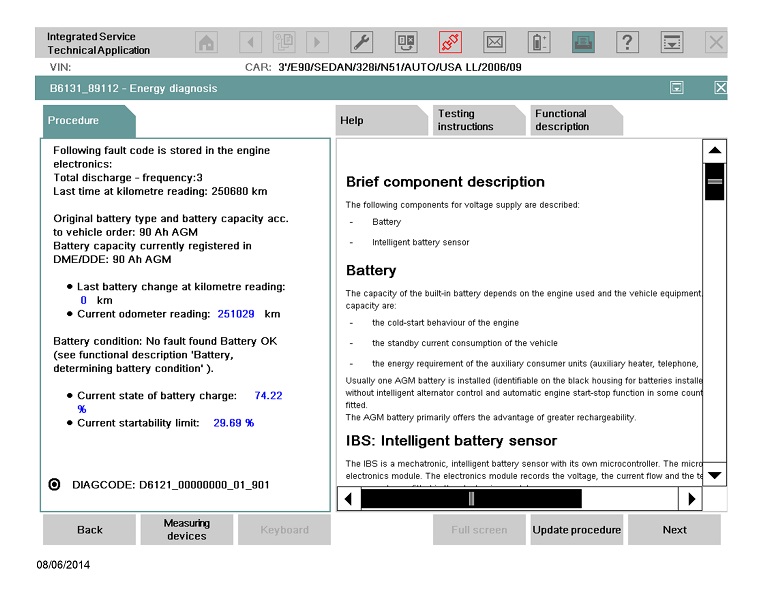
Result of the energy diagnosis

The procedure reads all the necessary data from the corresponding control units. After evaluating this data, it displays the following information:

Conspicuous information: this information is only displayed if there was a problem in the vehicle energy system. The number of information items varies. This information includes the possible causes of a flat battery or a vehicle electrical system fault. Look at the list of possible fault causes, then select the number of the relevant causes in order to bring up detailed information, instructions and the associated diagnosis codes. If there are several possible fault causes, they are listed in order of the kilometer reading at which they occurred (most recent first). For example: the vehicle does not ‘go to sleep’ (sleep inhibitor); the vehicle is wakened time and again; the side lights were switched on for too long, etc.
Standard information: This information can always be displayed (driving profile, stationary profile and – only if an IBS is fitted – evaluation of the closed-circuit current measurement data, information on the battery, for example battery charge state, of the last 5 days).

On the basis of this information, it can then be decided what the real cause of the fault is.
ISTA Energy diagnosis screenshotISTA Energy diagnosis

BMW-Energy-Diagnosis-1

Overview of possible causes

A breakdown due to a drained battery or a problem in the vehicle energy system is not necessarily the result of a faulty battery. The various causes for discharge of the battery can be placed in two main categories:

    Vehicle faults:
Vehicle does not assume sleep mode.
The vehicle keeps being woken up.
Standby current too high in rest state.
Faulty alternator (poor charge balance)
Faulty battery.

    Unfavorable customer behavior:
Side lights, parking light or hazard warning flashers were switched on for too long.
Terminal R or Terminal 15 switched on for too long
Long immobilization period.
Unfavorable driving profile (short-distance driving).
Frequent use of auxiliary consumers or use of auxiliary consumers for a longer period (increased power consumption at a standstill).

    Data from the vehicle that is read and evaluated

For energy diagnosis, the evaluated data in the vehicle is not changed. The energy diagnosis can be run a number of times and normally always provides the same result. The energy diagnosis normally provides the same result after repairs, as the data is still present in the vehicle. Even after deleting the fault memory, the data from the energy history memory is still stored. However, at the latest when the energy history memory is overwritten with new data, the repaired fault cause is no longer displayed as result of the energy diagnosis. This information in detail:
Energy history memory in the JBE (Junction Box Electronics) The energy history memory (NB: do not confuse with the history memory for fault entries) stores various bits of information that can assist in establishing the cause of problems with the vehicle energy system. The stored information of the energy history memory in detail:
The maximum number of waking’s within an off-load phase (terminal R off) within the last 5 weeks
The last 5 control units that prevented the vehicle from going to sleep (with kilometer reading of each event)
The driving profile of the last 5 weeks:
The driving profile is stored in the energy history memory with 6 data records. Each data record contains the following information: Starting time of record the data record, distance travelled in km during recording, number of journeys in different ranges. A new data record is started as soon as the time difference between the current time and starting time of recording of the current data record is greater than 7 days. This means the time span of the evaluation is usually approx. 35 days if the vehicle was not immobilized for a longer period without being wakened. When all 6 data records in the data memory are full, the oldest data record is overwritten.
As of model year 03/2007 (JBE2), the last CAN messages that woke the K-CAN bus (with kilometre reading of each event)
Fault code memory in the JBE
If a bistable relay is fitted, the causes of cutoff of terminal 30g-f are stored in the JBE. There are the following fault cases:
The battery reached the starting capability limit at terminal R off.
Up to model year 09/2006: 60 minutes after terminal R off, the vehicle has not yet switched into the rest state.
As of model year 03/2007: The vehicle is not yet in the idle state 10 minutes after cutoff of terminal 30g.
Up to model year 09/2006: The vehicle was wakened unexpectedly at terminal R off more than 30 times.
As of model year 03/2007: The vehicle was awakened unexpectedly more than 20 times after cutoff of terminal 30g.
Diagnosis requests of the DME/DDE
The DME/DDE stores various data that is used for the energy diagnosis:
If an IBS is fitted, the last 32 cycles of the closed-circuit current monitoring are stored
The last registered battery replacement
If an IBS is fitted, the state of charge of the battery of the last 5 days
The kilometre readings of the last 5 days
If an IBS is fitted, the auxiliary consumer units that were switched on during the last 32 cycles, for example, light or independent heating.
Fault memory in the DME/DDE – If an IBS is fitted, the DME/DDE stores a fault code memory entry in the event of a closed-circuit current fault and total battery discharge.
Fault code memory of the FRM (footwell module) – The FRM is responsible for control of the lights. At terminal R off, the FRM switches the lights off if the voltage falls below approx. 11 V. On cutoff, a fault entry is stored. At undervoltage, the FRM stores a fault code memory entry. The environment related conditions can be used to determine whether terminal R, terminal 15 or a statutory consumer unit (e.g. light or hazard warning lights) was switched on.

BMW-Energy-Diagnosis-2
BMW-Energy-Diagnosis-3

NOTE:

For the following vehicles the energy diagnosis test procedure should be worked through in the event of the complaint “flat battery”:

BMW-Energy-Diagnosis-4

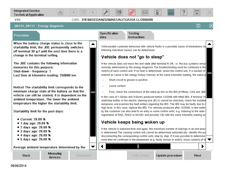
Unfavorable customer behavior with vehicle faults is a possible cause of breakdowns due to a depleted battery. In detail, the following individual causes can be determined:

Vehicle does not ”go to sleep”

If the vehicle does not reach the rest state after terminal R Off, i.e. the bus systems remain active, the causing control unit is normally determined by the energy diagnosis. The troubleshooting must be continued in the peripherals (e.g. faulty sensor or switch) of each control unit. If no fault is determined, renew the control unit. If a number of control units on the PT‐CAN bus are entered as cause in the energy history memory at the same kilometer reading, the wake-up line should be checked:

Short circuit to ground or positive
Loose contact
First, check the connections of the wake-up line on the IBS (if fitted), CAS and JBE

In the case of 1-Series and 3-Series produced before 12/2006 with fitted IBS: If terminal 15 can no longer be switched using the start/stop button or the electric steering lock (ELV) cannot be unlocked, check the installation location of the battery for traces of dampness and examine the fault entries regarding the IBS: The IBS may be faulty due to moisture and keep the wake-up line at high level. In this case, replace the IBS. For vehicles produced after 12/2006, a new water-tight IBS is used. Important! Operation by the customer can also lead to an entry in some control units: e.g. listening to the radio with terminal R OFF leads to the registration of RAD, RAD2 or M‐ASK and possibly CID with the same kilometer reading as cause in the energy history memory.

Vehicle keeps being woken up

If the vehicle is wakened time and again, the maximum number of waking’s in an rest phase (terminal R OFF) for the last 5 weeks is determined. The causing control unit cannot be determined automatically: Identify the possible cause by disconnecting fuses or disconnecting the corresponding control units step by step. If it was possible to determine the waking control unit, troubleshooting must then be continued in the peripherals (e.g. faulty sensor or switch, loose contact) of the control unit. If no fault is determined, the control unit must be renewed.

NOTE:

In exceptional cases, it is possible that the result ”Vehicle keeps being woken up” is generated by unfavorable customer behavior, e.g. frequently waking the vehicle at terminal R OFF by opening and closing the tailgate or doors.

Excessive standby current

The result ”Excessive standby current” means that the vehicle, occasionally at least, has had a standby current greater than 80 mA. Here, the vehicle was in the rest state, that is, the bus systems were inactive. A possible cause of this could be faulty control units. As troubleshooting, run a standby current measurement and identify possible causes by disconnecting fuses or disconnecting the corresponding control units step by step.

Battery or alternator faulty

Even though the battery was not the cause of the complaint, it might have been damaged beforehand due to total discharge for a longer period. For this reason, check the battery condition if you suspect that the battery might have been damaged beforehand. If there is a suspicion that the alternator is faulty, it must be determined whether the DME/DDE has relevant fault entries. Fault entries with regard to the IBS must also be taken into account. If the vehicle comes to a standstill and will not start during or shortly after a journey, the cause probably lies in the charge balance of the alternator. A requirement here is that the charged battery was still able to deliver adequate current for the starting operation.

E65, E66, E67 from model year 03/2004,-E60, E61, E63, E64, E70, E71, E72, E81, E82, E84, E87, E88, E89, E90, E91, E92, E93, -All F Series from F01, -All MINIs from R55, -RR04
If you want to know more about BMW ICOM information, please visit Obd2tool.com

2021年9月30日星期四

“Boot Strap” Error Occurs When Using DRB III to Flash TCM on 2001-2004 JR


VEHICLES:

*   2001-2004 JR 2.7L 41TE automatic transmission

SUGGESTIONS:

*   Verify the DRB III is at the latest release using TechTOOLS.
*   Verify the CH7000 red-ended cable is being used and is in good condition.
*   Verify that DRB III connections are clean and not damaged.
*   Verify the vehicle Data Link Connector (DLC) is not damaged and no pins are pushed out.
*   Check vehicle battery condition.
*   Repair any damaged wiring before flashing any ECU.
*   Verify all accessories are off while flashing controller.

If all the above items have been checked and there is still an issue with flashing the Powertrain Control Module (PCM), perform the following:

DRB III Cold Boot

*   Press the “Yes” and “More” buttons at the same time, then when prompted press the “F4” button to continue.
*   After the cold boot has been performed the flash file will have to be downloaded again from TechTOOLS.

Reseat DRB III PEP Module

*   The PEP module in on the back side of the DRB III and is opposite the DRB III screen.
*   To reseat, pull the DRB III out of the protective cover, turn it over, and slide the PEP module towards the top (connector) side to remove.
*   Repeat this several times to reseat the connectors.

Disconnect SCI Circuit from the BCM C1 Connector Cavity 10

*   Start the flash.
*   When the DRB III instructs you to turn the key off, remove the PK/LB SCI wire from the BCM C1 connector cavity 10.
*   After the PK/LB SCI wire from the BCM C1 connector cavity 10 has been removed, turn the key back on and continue the flash.
*   When the flash is finished, reinstall the PK/LB SCI wire removed from the BCM C1 connector cavity 10.


https://chryslertroublerepair.blogspot.com/2021/08/boot-strap-error-occurs-when-using-drb.html

How to Solve Xhorse Dolphin XP005 “Error 56, Error code 6”


Problem

I have successfully cut 3 keys via Xhorse Dolphin XP005 + VVDI Key Tool Max until the 4th key, it prompted “Error:56. The cutter is short-circuited, please check the cutter conductivity. Please take photo and send to technical support.”

The error still exits even if I use other devices to control Dolphin XP005, it occasionally occurs cutter detected error code: 6 as below

“Please do following steps

*   check the clamp is correct;
*   Check height level adjustment finished;
*   Check clamp calibration finished;
*   Check the key insert properly, no chips.”

I can’t use Dolphin XP005 machine anymore, I can’ do calibration or anything else. Please help me.

How-to-Solve-Xhorse-Dolphin-XP005-“Error-56,-Error-code-6”-1
How-to-Solve-Xhorse-Dolphin-XP005-“Error-56,-Error-code-6”-2

Solution
*   Just take apart the LED lamp cover to brush the scrap iron;
*   Do a electrical conductivity measurement after cleaning, take a video to VVDIshop engineer for help.


https://xhorse-tool.blogspot.com/2021/08/how-to-solve-xhorse-dolphin-xp005-error.html

2021年9月15日星期三

VXDIAG VCX SE Benz License Expired Solution


Here share the solution to resolve VXDIAG VCX SE Benz license expired problem.

Problem:
Hello, I’m getting again that license expired… Can you help me please? I try to update the license, but it prompts “update license failed. Retry! Error Code: 0”. Can you explain to me exactly how to do?

Vxdiag-Vcx-Se-Benz-Offline-Error-1
Vxdiag-Vcx-Se-Benz-Offline-Error-2

Obd2tool.com engineer replied:
You should connect the VCX SE BENZ interface firstly, and then update license in VX Manager. You need to update it every 60 days.

The customer’s feedback:
I’ve just done. It works! Thanks!

Super MB Pro M6 vs. C4 vs. C6


Do you know how to choose MB Star Diagnostic Tool? Here we have picked out 4 to make a comparison. Let’s find what are the differences between them. This post is available with Mercede Benz diagnostic tools, include reviews and comparison of Benz VCI C6, Benz OEM C6, Benz ECOM, SD Connect C4, SD Connect C4 Plus Doip, Xentry Connect C5 Doip.

Super MB Pro M6 vs. MB SD C4 Plus vs. SD Connect C4 vs. OEM MB C6

MB diagnostic tool reviews:

 Product Super MB Pro M6
MB SD Connect C4 Plus
SD Connect C4
OEM MB C6
Super MB Pro M6 MB SD C4 Plus SD Connect C4 OEM MB C6
Diagnosis Full System YES YES YES YES
Online Programe YES YES YES YES
Offline Programe YES YES YES NO
Brush to hide YES YES YES YES
Maintenance service YES YES YES YES
Xentry YES YES YES YES
DAS YES YES YES YES
HHTWIN YES YES YES NO
EPC YES YES YES YES
WIS YES YES YES YES
Vediamo YES YES YES NO
DTS Monaco YES YES YES YES
Star Finder YES YES YES YES
PL73 YES YES YES YES
SDmedia YES YES YES YES
Doip YES YES NO YES
Truck/BUS YES YES YES Portion
Firmware Update YES YES YES(Need to install batteries) YES
wire Direct connection Direct connection Point to point Direct connection
wireless LAN LAN LAN LAN/usb Cable
Software Version 2021.06 2021.06 2021.06 2021.06
Hardware Version OS:2.3, CSD:2.11 OS:2.3, CSD:2.11 OS:2.3, CSD:2.11 1.84
Heat dissipation Heat sink + fan Heat sink NO NO
Software Language

(Can switch directly)

ENGLISH, BULGARIAN, DANISH, GREEK, SPANISH, FRENCH, ITALIAN, KOREAN, POLISH, ROMANUAN, SERBO-CROATIAN, TURKISH, CZECH, GERMAN, FINISH, HYNGARIAN, JAPANESE, DUTCH, PORTUGUESE, RUSSIAN, SWEDISH, CHINESE

Super MB Pro M6
1. Perfectly replaces normal MB SD C4/C5
2. Supports Original Benz Dealer Diagnostic Software
3. Supports firmware update without installing the battery
4. Support Mercedes-Benz models, covering 12v car, 24v diesel truck & bus, MPV etc.

Benz VCI C6:
Benz VCI C6 OEM Xentry Mercedes Diagnostic Tool with Encrypted Dongle and Keygen, support new Mercedes Benz model and Doip protocol.

Mercedes Benz C6:
Mercedes Benz C6 OEM Xentry diagnosis VCI DOIP Pass thur interfac is the latest interface for For Mercedes & SMART vehicles can replace Star C4/C5. XENTRY Diagnosis VCI acts as a Pass-through Interface, also called MB Star C6, For Benz C6 multiplexer to provide complete communication between a vehicle and the XENTRY software loaded on a PC.

Mercedes Benz eCOM:

Mercedes Benz eCOM DoIP Box Multiplexer Kit Support DoIP for latest E and S series, MB eCOM DoIP diagnostic C5 Xentry Perfect for Perfect for Mercedes COMAND NTG5, NTG5s1, NTG5s2, NTG5.5

Sd Conenct C4:
New DOIP MB SD C4 Plus Mercedes Benz diagnostic tool is the only C4, support new Mercedes with doip, no battery need for firmware update. This Doip Benz Star C4 has better quality, wireless connection is stable, It’s waterproof, shockproof and tamper proof. Can work with original Mercedes Benz software.

SD Connect C4 Plus Doip:
Doip MB SD C4 Mercedes Benz Star Diagnosis Tool with Lenovo X220 Laptop,newest V2019.12 500GB Xentry Openshell XDOS software is pre-installed and activated, ready to use. Buy this bundle sales, not only help you save money, but also save time.

MB SD Connect C5 with DTS Monaco & Vediamo:
MB SD Connect C5 Support Wireless and Lan cable connection, With UDS Chip, support both K Line and CAN BUS Protocol, but also UDS Protocol,support Mercedes Benz cars and trucks after year 2000,Software will be installed and activated well before shipping, you can use it directly after you get it.